Image intensified fluoroscopy
Image intensified fluoroscopy is a precise design that helps the radiologist see pictures in real time as they happen this is especially useful in procedures like barium edemas and other studies of the intestines.Fluoroscopy displays the image on a television screen to be seen by the radiologist. Most fluoroscopy the x-ray tube is hidden under the table while the image intensifier is above the table. Some have the fluoroscopy above the table and image intensifier under the table.
Intensification principles/Characteristics
Images when you see them are very dark and are hard to see so to make for better diagnoses brightness gain came into effect. Brightness gain is the ability for the flourscope to increase the brightness. All brightness gain is the minification gain and the flux gain multiplied. The minification gain is the ration of the square of the diameter of the input phosphor to the square of the diameter of the output phosphor. So minification factor is the reduction in size on the input phosphor screen. The flux gain is the ration of the number of light photons at the output phosphor to the number of x-rays at the input phosphor. So basically if you change the minification factor or flux gain you are ultimately changing how bright the image will turn out to be. The conversion factor is the ability for the image intensifier to convert x-rays into visible light and is exspressed as output phosphor illmination/input exposure rate.
Automatic Brightness Control
Like the name it controls the brightness of the image by automatically varying the KVP and mA.

Multi-field image intensification
allows greater flexibilty in all fluoroscopic examination. In fluoroscopy without magnigifing an image it can be hard to see and hard to make a diagnosis. Tubes come in many sizes if the tube is a 28/19/14. If you are looking at the image in a 28cm mode the image doesn't look magnified but if you tranfer to the 19cm mode the image becomes more magnified because the images fills the entire screen so if you were to use the magnification factor 28/19=1.4 magnified and if you transfer to the 14 cm mode 28/14 the image will be 2 magnified. What this does to patient dose is it increases patient dose because you have to increase the mA.To figure out the patient does you square the diameter of the input phoshor and divide them for example 28squared/19squared is 2.1 times higher dose. The spatiel resolution is improved as the diameter of the phosphor goes down and the magnification goes up. In this mode the noise and the distortion of the objects goes down as the contrast and spatial resolution goes up.
Viewing and recording systems
The camera consists of a cylindrical housing about 15 mm in diameter by 25 cm in length.The television camera tube converts the light image from the output phosphor of the image intensifier into an electrical signal that is sent to the televisions monitor, where it is reconstructed as an image on the television screen. One way that you can convert the light from the output phosphor into an electrical image is the charge-coupled device (CCD).

Invented in 1970 CCD is used in video cameras as well as medical imaging.Invented to take the light from the output phosphor and turn it into an electronic signal that can be seen on T.V. The main advandtage of CCD is high spatial resolution, High signal-to-noise ration, High detective quantum efficiency(DQE), no warm up required, no lag or blooming, no spatial distortion, no maintenance, unlimited life, unaffected by magnetic fields, linear response,and lower patient dose. In order to see the image you need a television monitor which amplifies the signal. The radiologist can control the picture on the monitor by controling the contrast and the brightness of the image. The television monitor is made up of a television picture tube which is used to focus and steer the electron beam that is made up of a glass envelope, electron gun, and external coils. The next part of recording is have a spot film which is positioned between the patient and the image intensifer. This requires a higher mA since fluroscope use such a small mA inorder to get the larger mA it takes a couple of seconds for the anode to start spinning faster.The Photospot camera uses film sizes of 70 to 105mm. As a general rule, larger film format results in better image quality but at increased patient dose. The photspot camera doesn't interupt fluoroscopic filming and can take pictures up to 12 pictures per second.
Digital Fluroscopy
Digital Fluroscopy was discoved in 1970. This was to place a computer between the T.V. camera and the T.V. monitor. Advantages of Digital fluroscopy over conventional fluoroscopy include the speed of image acquisition and postprocessing to enhance image contrast. In digital fluoroscopy a computer has been added to have multiple monitors and a more complex operating console.The output signal from the image intensifed sigital image recepter is transmitted to an analog to digital converter. The ADC takes the analog signal and turns it into an digital one.

The Charged coupled device was a big step from conventional fluoroscopy to digital instead of the TV camera pickup tube they use a CCD. The flat panel image display are easier to view and easier to manipulate and they provide better images. They are light in weight and easy to see and can be readily mounted suspended in an angiographic room.
Operation and Techniques
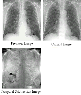
The principal advantage of DF examinations are the image subtration techniques that are possible and the enhanced visualization of vasculature. Image contrast is also enhanced electronically. Temporal subtraction is when you can subtract different organs or bones to see vessels that have been filled with contrast better two methods of doing this is mask mode and time interval difference mode.


